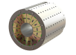
Voice coil motors (VCMs), also known as voice coil actuators, are electromagnetic actuators used for precise linear or limited-angle motion. They generate force through the interaction between current-carrying coils and permanent magnetic fields, providing fast response, smooth motion, and accurate force control for positioning, vibration, and other motion applications.
Magnetic assemblies in VCMs typically combine permanent magnets with steel yokes or pole pieces to guide and concentrate magnetic flux through working air gaps. Cylindrical designs can use different magnetization arrangements and magnetic circuit structures to create the required radial field in the working region.
Cylindrical and Flat Voice Coil Motors
Voice coil motors are commonly built in cylindrical or flat configurations. The difference is more than the external shape, as each arrangement provides a different layout for the coil, permanent magnets, magnetic return path, and working air gap.
Cylindrical voice coil motors use a coaxial structure with an annular working area around the motor axis. The magnetic circuit creates a radial field across this area, allowing the current-carrying coil to generate force along the axis. Different magnet shapes, magnetization directions, and steel components can be used to produce this field.
Flat or rectangular voice coil motors arrange the coil and magnetic circuit in a flatter layout. These designs can be useful where available space, mounting dimensions, or the required motion favor a lower-profile structure. Their magnet arrangements and magnetic return paths can therefore be quite different from those used in cylindrical designs.
Cylindrical voice coil motors are particularly interesting from a magnetic design perspective because the required radial field can be produced through several different magnetic circuit configurations.

Cylindrical and Flat Voice Coil Motors
In cylindrical voice coil motors, the useful magnetic field in the annular working air gap is primarily radial, allowing the current-carrying coil to generate force along the motor axis. However, this radial working field can be created using magnets with very different magnetization directions and magnetic circuit arrangements.
In practice, cylindrical VCM magnetic circuits can be understood through three broad approaches: radially magnetized configurations, axially magnetized magnet-and-yoke configurations, and more complex mixed-magnetization or flux-focusing configurations. The important distinction is not simply the shape of the magnets, but how the complete magnetic circuit delivers flux into the working air gap.
Radially Magnetized Configurations
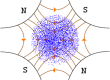
Radially magnetized ring magnets provide the most direct route to the required radial working field. Their magnetic poles are distributed between the inner and outer cylindrical surfaces, allowing continuous rings to generate radial flux around the full circumference of the working air gap.
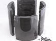
Similar magnetic circuits can also be assembled from diametrically magnetized arc magnets arranged around the circumference. The magnetization direction within each arc magnet is essentially fixed, so the assembled structure approximates the continuously varying magnetization direction of radially magnetized rings.
This segmentation introduces circumferential field ripple and harmonic components, with the resulting field distribution depending on the number of segments, assembly gaps, and positioning accuracy.

Continuous radial rings eliminate the physical joints between individual magnets and can provide better circumferential field continuity. Segmented designs, however, are often easier and less expensive to manufacture and magnetize, particularly when larger dimensions, thicker walls, higher magnetic grades, or specialized radial magnetization would increase the cost and difficulty of producing continuous rings. The final trade-off therefore involves not only magnetic performance, but also magnet manufacturing cost, assembly cost, dimensional tolerances, and production volume.
Axially Magnetized Magnet-and-Yoke Configurations
Axially magnetized magnets can be combined with steel yokes and pole pieces to guide and redirect magnetic flux into the annular working air gap. The magnets provide the magnetic source, while the surrounding soft magnetic components establish the return path and redirect the flux to produce a predominantly radial field in the working region.
In these configurations, the steel components are an active part of the magnetic circuit rather than simply mechanical supports. Yoke and pole-piece geometry, air-gap width, and local magnetic saturation all influence how much useful flux reaches the coil and how uniformly it is distributed.

This illustrates an important point in voice coil motor magnetic circuit design: the magnetization direction of the permanent magnets does not necessarily have to match the direction of the useful magnetic field in the working air gap.
Mixed-Magnetization and Flux-Focusing Configurations
More complex magnetic circuits can combine magnets with different magnetization directions to concentrate useful flux in the working air gap. Radially and axially magnetized magnets may be used together, while Halbach-like arrangements and other flux-focusing structures provide additional ways to control the field distribution.
In Halbach-like arrangements, radially magnetized magnets contribute directly to the radial working field, while axially magnetized magnets help redirect and concentrate more flux toward the working air gap.
The combined arrangement can increase useful air-gap flux, reduce leakage, or shape the magnetic field over a specific working region.

The trade-off is greater structural and manufacturing complexity. More magnets, multiple magnetization directions, tighter positioning requirements, and more complicated assembly processes can all increase cost and make magnetic consistency more difficult to control.
What Determines the Working Air-Gap Field in Voice Coil Motors
In voice coil motors, the useful magnetic parameter is the magnetic flux density in the working air gap where the active coil conductors interact with the magnetic field. For a given coil geometry and current, the available air-gap flux density has a direct influence on force generation, while the surface field of the magnets alone is not a reliable indication of VCM performance.
In cylindrical VCMs, the active conductors interact with an annular radial field as relative motion occurs along the motor axis. Magnet length, pole geometry, and the axial distribution of the air-gap flux density therefore need to match the required working stroke. Designs optimized only for maximum flux density near the center of the magnetic circuit may produce greater force variation toward the ends of the usable travel.
The radial clearance of the annular air gap is another important design parameter. Smaller gaps can support higher flux density, but they also leave less room for coil dimensions, mechanical clearance, alignment, and assembly tolerances. Poor concentricity between the coil and magnetic structure can create an uneven air gap around the circumference, resulting in corresponding variations in local flux density.
Pole-piece geometry and the ends of the magnetic circuit also influence how quickly the air-gap flux density falls as the working position approaches the limits of the magnetic region. Magnet dimensions and yoke geometry therefore need to be considered together with the required stroke rather than being selected simply to maximize flux density at one position.
For VCM magnetic assemblies, the practical target is sufficient and reasonably uniform air-gap flux density over the required working stroke, while maintaining realistic radial clearance, concentricity, magnetic saturation margins, and assembly tolerances.
Custom Magnetic Assemblies for Voice Coil Motors
Voice coil motor projects can involve very different magnet geometries, magnetization arrangements, yoke structures, and working air-gap requirements. The appropriate solution depends not only on the magnets themselves, but also on how the magnetic circuit is expected to deliver the required flux density over the working stroke.
If you are developing or modifying a VCM, SDM can support the discussion based on existing drawings, magnet specifications, magnetic circuit structures, target air-gap flux density, or prototype assemblies. Requirements involving radially magnetized rings, segmented magnet arrangements, axially magnetized magnets, steel magnetic components, and other custom magnetic configurations can be evaluated according to the specific project.