What Are Sensor Magnets?
Sensor magnets are permanent magnets or magnetic assemblies used to provide a detectable magnetic field for sensing, switching, positioning, speed measurement, or angle feedback. They work with different magnetic sensing technologies and systems, including Hall sensors, reed switches, anisotropic magnetoresistive (AMR), giant magnetoresistive (GMR), and tunnel magnetoresistive (TMR) sensors, as well as magnetic encoder systems used for position, speed, and angle feedback.
In these applications, magnets are not simply standard parts placed near a sensor. Their material, shape, size, magnetization direction, magnetic output, and assembly position can all affect sensor response.
Small changes in air gap, dimensional tolerance, temperature, housing thickness, or installation position may influence the signal received at the sensing position.

Sensor magnets are used in position sensing, speed sensing, angle detection, switching, level sensing, and flow measurement. These functions can appear in automotive systems, industrial automation, robotics, consumer electronics, medical devices, and compact electromechanical assemblies.
Depending on the sensing method and available space, sensor magnets may be produced in disc, cylinder, block, or ring shapes. They can be axially, diametrically, or multipole magnetized, and may also be supplied as overmolded components or custom magnetic assemblies.
For magnet suppliers, the key task is not to design the complete sensor circuit, but to provide magnets that can deliver the required magnetic field direction, strength, and stability at the target sensing position. This makes sensor magnet design closely related to air gap control, magnetization accuracy, dimensional tolerance, material selection, and magnetic simulation.
Why Magnet Design Matters in Magnetic Sensing?
Using the right sensor does not always guarantee the right result. Even with the same sensor model, unsuitable magnets or poor installation conditions can lead to unstable performance.
Magnetic output at the sensing position is often more important than the nominal strength of the magnets themselves. A magnet that appears strong at the surface may still fail to provide the required field at the actual sensing distance.
Air gap, mounting offset, housing thickness, nearby metal parts, temperature, and dimensional tolerance can all influence the magnetic field received by the sensor. In practical applications, these variations may cause inconsistent switching distance, weak signals, angle error, or poor repeatability.
For this reason, selecting sensor magnets usually involves more than choosing a material grade. Magnet shape, magnetization direction, field distribution, assembly method, and working distance should all be reviewed during the design stage to reduce trial-and-error later.
Common Sensor Types and Magnet Requirements
Sensor magnets are used with different sensing technologies, and each sensor type may have different requirements for magnetic field strength, direction, distance, and stability. From the magnet supplier’s perspective, the main concern is not the internal circuit design, but whether the magnets can provide a suitable and repeatable magnetic field at the sensing position.
Hall sensor magnets are widely used for position detection, speed sensing, switching, and motor feedback. These applications usually require magnets with controlled polarity, stable magnetic output, and suitable field strength at the working air gap. Magnet size, grade, and magnetization direction should be matched with the sensor threshold and installation distance.
Reed switch magnets are often used in simple switching applications, but their design should not be treated casually. Pull-in distance, release distance, magnet orientation, installation position, and surrounding metal parts can all affect switching reliability. In many projects, a small change in magnet position may lead to early triggering, delayed release, or unstable switching.
AMR, GMR, and TMR sensor magnets are used in more sensitive position, angle, and motion detection applications. Compared with simple switch-type sensors, these magnetoresistive sensors often place higher demands on magnetic field direction, field distribution, signal stability, and assembly accuracy. The magnets should be designed with attention to air gap, eccentricity, temperature stability, and the required field pattern.
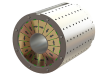
Magnetic encoder magnets are used for rotary position feedback, speed measurement, and angle detection. They may use diametrical magnetization, axial multipole magnetization, radial multipole magnetization, or customized magnetic pole patterns. For magnetic encoder rings, pole number, pole pitch, magnetization accuracy, concentricity, and runout can all influence the final signal quality.
In practical sensor projects, the same magnet shape may behave differently when used with different sensor types. For this reason, sensor magnet selection should be based on the sensing method, working distance, required signal behavior, assembly structure, and operating environment.

Hall Sensor Magnets

Reed Switch Magnets

Magnetoresistive Sensor Magnets

Magnetic Encoder Magnets
Common Magnet Designs for Sensor Applications
Sensor magnets can be designed in many forms depending on the sensing method, available space, installation structure, and required magnetic field direction. In simple switching or detection applications, standard shapes such as disc magnets, cylinder magnets, block magnets, and ring magnets are commonly used.
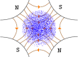
For position, speed, and angle sensing, magnetization direction becomes especially important. Sensor magnets may be axially magnetized, diametrically magnetized, radially magnetized, or multipole magnetized depending on how the sensor reads the magnetic field. The same magnet shape can produce very different sensing results when the magnetization direction changes.
In compact or high-precision applications, sensor magnets may also be integrated into plastic parts, metal housings, shafts, rotors, or custom magnetic assemblies. These designs help control installation position, protect the magnets, reduce assembly variation, and improve repeatability during use.
For magnetic encoder, rotary feedback, and speed sensing applications, multipole ring magnets and magnetic encoder magnets are often used to generate repeated magnetic signals along a circular path. In these cases, pole number, pole spacing, magnetization accuracy, concentricity, and assembly position should be considered together with the sensor layout.
The best magnet design is not always the strongest magnet or the most complex structure. It should match the sensor type, sensing distance, mechanical space, temperature condition, and expected signal behavior.
Key Design Factors for Sensor Magnets
Sensor magnets should be designed according to the actual sensing condition, not only by material grade or magnet size. In many applications, the most important question is whether the magnets can provide the required magnetic field direction and magnetic output at the sensing position.
Magnetic output at the sensing position is often more useful than surface field alone. The sensor does not read the magnet at the pole surface, but at a certain working distance. If the magnetic field is too weak, the sensor may fail to trigger or provide a stable signal. If the field is too strong, it may cause saturation, nonlinear output, or signal distortion in some sensor systems.
Air gap and working distance should be reviewed carefully. The actual air gap may include not only the designed distance between the magnets and the sensor, but also coating thickness, adhesive layers, plastic housings, protective covers, and assembly tolerances. These factors can reduce the magnetic field received by the sensor.
Magnetization direction is another key factor. Axial, diametrical, radial, and multipole magnetization patterns create different magnetic field distributions. The correct magnetization direction depends on how the sensor is positioned and which magnetic field component it needs to detect.
Dimensional tolerance and assembly accuracy can strongly affect repeatability. Small changes in magnet position, tilt, eccentricity, or distance may lead to different sensor responses, especially in angle sensing, speed feedback, and magnetic encoder applications.
Temperature stability should also be considered. Magnetic output changes with temperature, and irreversible loss may occur if the magnets are exposed to unsuitable operating conditions. For high-temperature or long-term reliability requirements, material selection and magnetic performance margin become especially important.
Surrounding structures may influence the final magnetic field. Nearby steel parts, shafts, housings, screws, or shielding structures can change the magnetic path and affect the field received by the sensor. For this reason, sensor magnets should be reviewed together with the surrounding assembly whenever possible.
In practical projects, these factors are closely connected. A stronger magnet grade cannot always solve a sensing problem if the air gap, magnetization direction, assembly position, or surrounding structure is not suitable.
| Design Factor | Why It Matters |
|---|---|
| Magnetic output at sensing position | Determines whether the sensor receives enough usable field |
| Air gap and working distance | Directly affect signal strength and stability |
| Magnetization direction | Controls how the sensor reads the magnetic field |
| Tolerance and assembly accuracy | Affect repeatability and angle or speed feedback |
| Temperature stability | Influences magnetic output and long-term reliability |
| Surrounding structures | May change the magnetic field path |
Magnetic Simulation Support for Sensor Magnet Design
Magnetic simulation can be useful when sensor magnet performance cannot be judged by magnet grade or dimensions alone. In many sensing applications, the key concern is the magnetic field received at the actual sensing position, not only the magnetic output on the magnet surface.
Through magnetic simulation, different magnet sizes, materials, magnetization directions, and air gap conditions can be compared before sample production. This helps estimate whether the proposed magnet design can provide a suitable magnetic field strength and direction for the sensor layout.

Simulation is especially helpful for applications involving angle sensing, speed feedback, magnetic encoder magnets, compact assemblies, or limited installation space. It can also be used to review the influence of housing thickness, assembly offset, nearby steel parts, or other surrounding structures on the magnetic field distribution.
For custom sensor magnets, simulation does not replace prototype testing or the customer’s electronic and sensor system validation. The complete sensing system is usually designed and verified by the customer’s engineering team. Our role is to support the magnet side of the application by reviewing magnetic field distribution, air gap, magnetization direction, material selection, and manufacturability.
However, magnetic simulation can reduce unnecessary trial-and-error by identifying potential design risks at an earlier stage, such as insufficient field strength, unsuitable magnetization direction, excessive air gap, or possible signal inconsistency.
At SDM Magnetics, magnetic simulation can be combined with material selection, magnetization feasibility review, prototype production, and magnetic field inspection to support more reliable sensor magnet development.
Material Options for Sensor Magnets
The material selection for sensor magnets depends on the required magnetic output, available space, working temperature, environmental conditions, magnetization pattern, and cost target. Different magnetic materials can be used in sensing applications, but each material has its own advantages and limitations.
Neodymium (NdFeB) magnets are often used when compact size and high magnetic output are required. They are suitable for many small sensor magnets, position sensors, magnetic encoders, and compact electronic assemblies. However, coating protection, operating temperature, and irreversible loss should be reviewed carefully, especially in demanding environments.
Bonded magnets are also widely used in sensor applications, especially where complex shapes, thin sections, integrated structures, or multipole magnetization are required. Compared with sintered magnets, bonded magnets usually have lower magnetic output, but they offer better shape flexibility and can support more complex magnetic pole patterns.
Samarium Cobalt (SmCo) magnets are suitable for sensor applications that require better temperature stability, corrosion resistance, and long-term reliability. They are commonly considered when sensor magnets must work in high-temperature environments or where stable magnetic output is more important than the lowest material cost.
Ferrite magnets can be used in cost-sensitive sensing applications where space is less restricted and very high magnetic output is not required. They are often suitable for simple switching, detection, or position sensing designs, especially when the system can tolerate a larger magnet size.
AlNiCo magnets may be used in certain traditional sensing applications because of their good temperature stability. However, their low resistance to demagnetization means that shape, length-to-diameter ratio, working point, and surrounding magnetic circuit should be considered carefully.
In many sensor projects, the best material is not simply the strongest one. A suitable sensor magnet material should match the required magnetic field at the sensing position, operating temperature, mechanical space, magnetization pattern, assembly method, and expected reliability of the final device.
| Material | Main Advantage | Typical Sensor Magnet Use |
|---|---|---|
| Neodymium Magnets | High magnetic output in compact sizes | Small sensor magnets, encoder magnets, compact assemblies |
| Bonded Magnets | Shape flexibility and complex magnetization patterns | Encoder rings, sensor rotors, multipole magnets, integrated sensor parts |
| Samarium Cobalt Magnets | Better temperature stability and corrosion resistance | High-temperature or reliability-critical sensor applications |
| Ferrite Magnets | Cost-effective and stable | Simple switching, detection, and larger sensor designs |
| AlNiCo Magnets | Good temperature stability | Traditional sensing applications with suitable geometry |
Custom Sensor Magnets and Magnetic Assemblies
Custom sensor magnets are often required when standard magnets cannot meet the required sensing distance, magnetic field direction, assembly space, or signal stability. In these projects, magnet design should be reviewed together with the sensor position, mechanical structure, working temperature, and installation method.
At SDM Magnetics, sensor magnets can be customized in different materials, shapes, sizes, coatings, and magnetization directions. Depending on the sensing requirement, magnets can be axially magnetized, diametrically magnetized, radially magnetized, or multipole magnetized. For encoder, speed feedback, and angle sensing applications, customized magnetic pole patterns can also be reviewed according to the sensor layout.
Sensor magnets may be supplied as individual magnets or as part of magnetic assemblies. In some projects, magnets are integrated with plastic parts, metal housings, shafts, rotors, or other mechanical components to improve positioning accuracy, protection, and assembly repeatability.
For custom projects, magnetic simulation, magnetization feasibility review, prototype production, and magnetic field inspection can help reduce design uncertainty before mass production. This is especially useful when the application involves a limited air gap, compact structure, special magnetization pattern, or strict signal stability requirement.
The final goal is not only to produce magnets with the correct dimensions, but to provide sensor magnets that can deliver suitable magnetic output and stable performance at the actual sensing position.
Information Needed for Sensor Magnet Inquiry
For custom sensor magnets, clear application information helps us review the magnet design more accurately. If available, customers are encouraged to provide drawings, sensor layout, working distance, and basic performance requirements at the beginning of the project.
Useful information includes the magnet shape, size, material preference, magnetization direction, required magnetic field strength, sensing distance or air gap, operating temperature, and assembly method. For magnetic encoder magnets or speed feedback applications, pole number, pole pair number, rotation speed, sensor position, and signal requirements may also be important.
If the magnet will be installed inside plastic parts, metal housings, shafts, rotors, or other assemblies, the surrounding structure should also be considered. Coating thickness, adhesive layers, housing thickness, and nearby ferromagnetic materials may all affect the magnetic field received by the sensor.
Even if the final magnet design has not been confirmed, preliminary information can still help us evaluate material options, magnetization feasibility, magnetic simulation requirements, prototype direction, and possible production risks. This allows the sensor magnet design to be reviewed earlier and helps reduce unnecessary trial-and-error during development.