Ι What Is Magnet Skewing?
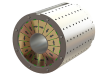
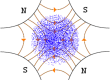
Magnet skewing is a specialized engineering technique used in permanent magnet rotors to ensure a smooth transition of magnetic flux as the rotor poles interact with the stator teeth. In a conventional straight-pole configuration, the entire magnet face enters and exits a stator slot simultaneously. This abrupt engagement creates a “jerky” magnetic pull known as cogging torque, which leads to significant mechanical vibration and noise during motor operation.
By contrast, a skewed arrangement intentionally offsets the magnet segments along the rotor’s axis. This gradual engagement effectively “smears” the magnetic transition, suppressing the mechanical vibrations and acoustic noise that often plague high-performance applications.

Consequently, magnet skewing is a critical necessity for improving NVH (noise, vibration, and harshness) and achieving a more sinusoidal back EMF waveform, both of which are essential for precision motor control.
Continuous Skewed Magnets vs. Step Skewing
While continuous skewed magnets are theoretically designed to produce a seamless magnetic flux transition, their application is often constrained by the physical dimensions of the motor rotor. In high-performance motor designs, the rotor length along the Z-axis frequently exceeds the standard manufacturing limits for a single, integrated skewed component. This mechanical constraint makes the use of a one-piece skewed magnet impractical for many large-scale or high-torque applications.
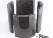
Since long rotors inherently require segmentation to maintain structural stability and precision, the engineering logic shifts toward step skewing. If a rotor must be divided into multiple segments along its axis anyway, utilizing standard, non-skewed arc magnets is the superior and more economical strategy. By implementing a precise angular offset between these standard segments during the assembly process, engineers can achieve electromagnetic performance that is virtually identical to a continuous skew.

Furthermore, because these segments typically feature diametric magnetization, the magnetic consistency across the rotor is exceptionally stable. This makes step skewing the definitive industry standard for balancing high-tier motor performance with mass-production efficiency.
Beyond Linear: Addressing Axial Force with V-Shape and Zig-Zag Magnet Skewing
Although linear step skewing is highly effective at reducing torque ripple, it introduces a problematic side effect known as axial force or axial thrust. Because the magnets are tilted in a single direction, the magnetic interaction creates a resultant force that pushes the rotor along the shaft. If left unaddressed, this constant thrust can cause premature bearing wear, increased friction, and mechanical instability, particularly in high-speed applications.
To counteract these parasitic forces, advanced rotor designs employ V-shape magnet skewing. By arranging the magnet segments in a symmetrical “V” formation, the axial thrust generated by the upper half of the rotor is precisely neutralized by the opposing force from the lower half. This self-canceling geometric arrangement is considered the industry benchmark for high-performance traction motors and electric vehicle powertrains, where protecting the bearings from axial loads is paramount.

For applications requiring even more refined control, such as high-precision robotic servos or medical equipment, zig-zag magnet skewing (also known as multi-stage crossover magnet skewing) provides a superior level of optimization. While a simple V-shape addresses the primary axial force, a zig-zag configuration utilizes multiple segments to target and cancel out specific higher-order harmonics in the magnetic flux. This results in an exceptionally smooth torque profile and minimal electromagnetic vibration. Although this pattern increases the complexity of the rotor assembly, the gain in stability and near-silent operation makes it a critical choice for systems where precision is the top priority.